 Tweet
Tweet
Hi guys dose anyone have the astra gte 16v cooling system diagram please
-
-
Re: GTE 16v cooling system diagram
vinci made one, i'm sure he'll see this -
Re: GTE 16v cooling system diagram
Okay can u pm him for me pls?Comment
-
Re: GTE 16v cooling system diagram
Go into your PMs, type Vinci in recipient box and his name will pop up, send msg and boom.Comment
-
Re: GTE 16v cooling system diagram
Here:

There could be differences in the connections on the plastic gallery that goes behind the block, the original GTE 16V had a different spot for the connection to the bottom of the header tank, closer to it. My engine had a Calibra gallery, that's what the drawing was based on.
All coolant hoses have an arrow for flow direction, if not then it is a vacume/air hose...Last edited by Vinci; 08-06-2014, 12:06 PM.Comment
-
Re: GTE 16v cooling system diagram
Here's the pipes I mean:

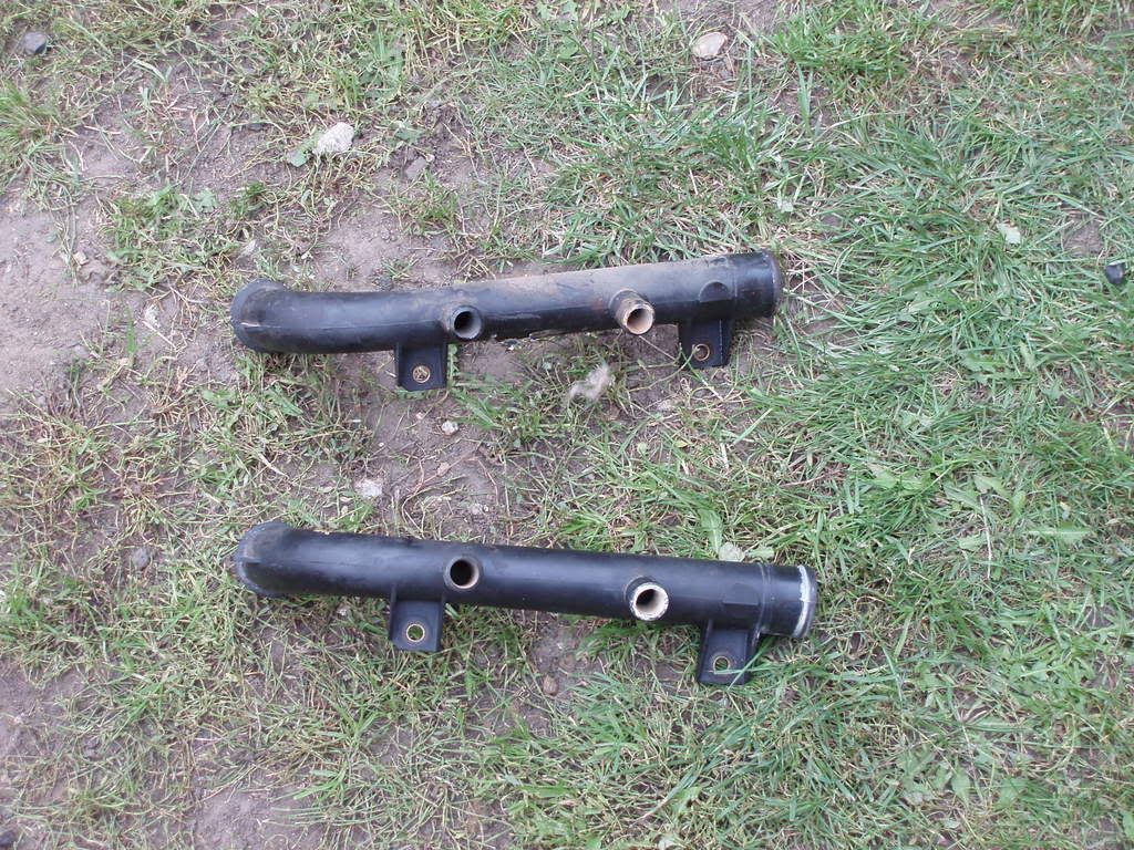
These pipes just join the hoses, so this doesn't have any influence, just need the right hoses for the right pipe...Comment
-
Re: GTE 16v cooling system diagram
Ok mate cheers is this for the gte 16v i think mine has been tampered with in the past as on mine Is abit diff il put i back together like this thoughComment
-
Re: GTE 16v cooling system diagram
Hi yes on mine i think the resvour gose to where you have number 3 and number 3 on mine gose to where you number 1 Is and my number 3 goes to your number 2 if that makes any senceComment
-
Re: GTE 16v cooling system diagram
Yep,16v as pictured, you may freely swap hoses on the gallery if it fits any better in your car and hoses as long as they connect to all the bits...Comment
-
Re: GTE 16v cooling system diagram
Ok vinci cheers for your help mate so do you think i could get away with puttin mine back together like your drawing mate??Comment
-
Re: GTE 16v cooling system diagram
Well sure, I'm doing it and mine cools superbly!Comment
-
Re: GTE 16v cooling system diagram
Ok cheers mate nice one il put it back together like you have drawn should work ok as it is a c20xe and your layout looks the same apart from the hoses that i said about mateComment
-
Re: GTE 16v cooling system diagram
Will be fine mate, heater matrix flow can also be swapped at will. The system basics are not that complex if you know how it is done. Basically there is the pump at the end of the plastic pipe that pushes all the fluid in to the block that it collects from the plastic pipe. Then there are three main loops, one very short goes right in to the intake manifold and back in to the three way 'gut' that is between the plastic pipe and pump entrance. Then there is the main unregulated loop through the head that exits above the gearbox, in to the heater matrix and back in to the pipe/pump. This is a short loop to allow fast engine warm up. And as soon as the latter is achieved there is a valve opened (the thermostatic valve) in to the little thick hose at the radiator. Then the cooled fluid flows back in to the plastic pipe again through the thick hose exiting the rad. Above that a thin hose exits the rad to bleed any air out of the system in to the header tank. The other small hose next to it on the header tank receives fluid from a fourth tiny loop from the throttle body pre-heater joint and that comes from a little exit right above the pump from the intake manifold short loop I described first.Last edited by Vinci; 24-05-2013, 07:09 PM.Comment
-
Re: GTE 16v cooling system diagram
Ok mate got it il be setting mine up exacly like yours mate when did you do yours??Comment
-
Re: GTE 16v cooling system diagram
Drive mine like that since the first GTE I've owned and that's a few years back now.Comment
Comment